IE010309A
Chapter 6
Aerodynamic Theory Revisited
Putting The Basic Airflow Force Equation To Use
The Smith-Putnam Machine
During the years of 1941 through 1945 one of the U.S.'s first great experiments in converting energy from the wind was conducted atop a peak in Vermont called "Grandpa's Knob" with the Smith-Putnam 1.25 Megawatt wind machine. Other machines in other nations had been put up that had utility-grade capacities but this was noteworthy for its having some significance in advancing the state of the art. The project was conceived and organized by an engineer named Palmer Coslett Putnam. News of this development was lost in the background of the news coming from the fronts of the war going on during much of this time. When nuclear energy appeared in the form of the bombs detonated also during these years, wind energy slid into further obscurity. The stories passed down about the machine indicated that it was a downwind machine with pitchable blades, it had a synchronous generator, and it fed energy into the New England utility power system, frequently running at full power. For the record, below is reproduced a photo of this unlikely assemblage of steel.
The 1.25 MW Smith-Putnam Wind Turbine Near Rutland, Vermont In 1941
To be noticed is how the blades were designed. Such great reliance was then placed on the munificence surrounding the very special aerodynamic shape of the aircraft wing airfoil that its use replicated here seemed to override and preclude any necessity to introduce other design features in the blades to tailor them for use on wind turbines. Even the chord width taper and pitch twist along their lengths from root to tip was not found. In fact, the blades resemble very much nothing other than aircraft wings themselves. A good view of the airfoil cross section of the blades is provided below, an enlargement of the blade tip shown at the top of the previous photo, the classic aviation Clark Y profile.
Detail of Blade Tip From The Previous Photo
The Mass Of Air
This airfoil shape may or may not be the optimum shape for wind turbine blades but its use to provide lift for aircraft, not to mention for birds, is beyond questioning. Material previously discussed adds new elements to the picture of just what it is that allows them to do their jobs efficiently. Recall that some time was spent discussing the mass of the air and the concept of airflow deflection. Here is where these ideas will see their first application in what is to follow. Discussions of aerodynamic lift ordinarily treat air mass as a function of air density, at a little over one ounce per cubic foot. But we saw that, taken in larger amounts, air masses range to the thousands of tons and even millions of tons, something not to be taken so lightly and certainly more along the lines of something that can explain how aircraft of hundreds of tons dead weight can be supported by it while in flight.
Airflow Deflection
Deflection is also new. In the way of abstract summary, it can be said herein that it is airflow deflection that is finally given its due. Those who are particularly taken with the idea that all airflow force is something that arises out of the same effect that causes baseball pitches to curve will be happy to learn that the "Magnus Effect", normally ascribed to as the originating mechanism, is also caused by the selfsame deflection, the one cause of all these effects together.
The Basic Aerodynamic Equation
But let's do this the way it is supposed to be done. The Basic Airflow Force Equation derived in Chapter 1 is repeated below:

The "F" Term
The terms can be taken one at a time for analysis. On the left hand side is the vector quantity, F, which represents the force. Little needs be said about this. The total force acting on an object such as an aircraft wing is often not in the vertical direction and so only the vertical "component" of it, i.e. the vector in a vertical direction that is found by removing the horizontal or "drag" component by vector subtraction, can be referred to as the "lift". Putting this another way, the total force vector, having been found by means of the above equation, can then be resolved simply into its lift (vertical) and drag (horizontal) components with vector algebra.
The "dm/dt" Term
The dm/dt factor is the calculus derivative referring to the total mass flow per unit of time. This is the brute quantity of total mass flow, no nonsense. What goes into making up this parameter? Well, the flow velocity for one, and the density of the flow for another, but much more than this, the whole frontal area the airfoil, along its full length, sees from some distance below to some distance above that is in any way affected by its passage and this can be very large. So this can be simply expressed as a formula by multiplying the air density times an area constant times the velocity of flow all of which looks like this: rCAV. We know what r is; we know the velocity, V; but A, while quite large, is often only guessed at and therefore use is made of a constant, C, to put this term to bed. C is determined for a wide class of problems and remains the same for the entire class, a relatively well-behaved sort of thing, even allowing the A to be dropped so that our final result is: rCV.
The "ÑV" Term
This brings us to the last term: ÑV.
This, like the force, F, is a vector. The "Ñ" is vector
algebra argot meaning "the vector difference of a vector before and after a
change to it" and is used here to refer to the difference vector between the
beginning velocity vector of a flow process and the same velocity vector at the
end of the process. This, by the way, is the secret of success of this equation.
Whereas, before, all analyses provided to the student reviewed the airfoil point
by point across its surface from the leading edge to the trailing edge, an
unnecessarily complex way of solving individual problems, this equation ignores
all that goes on in the intermediary stages, asking instead only that the
situation at the beginning and at the end of the process be known. This is, of
course, a much better way of solving problems and has much greater intrinsic
heuristic advantages as well, once again making a case for the benefits of
calculus well applied in solving problems.
Further simplifying things,
the velocities in this case, for the airfoil lift problem, are of the same
magnitude at the beginning and end of the flow over the wing and are different
only in their direction, arising from the aforesaid airflow deflection. Vector
subtraction then, something discussed before, is just a matter of drawing a
vector from the tip of the "before" vector to the tip of the "after" vector,
just bridging the gap, in other words, that arises because of this difference of
direction.
The Sine Qua Non Of Flight
Something must be said about this. In ordinary classical analyses the wing airfoil is drawn with its bottom surface, flat - as is the custom of depicting it, horizontal and parallel to the airflow. It "seems" right that the flow should thereby continue on straight as an arrow at the trailing edge undeflected. But this is where this treatment differs in its approach. Since the flow coming down off the top of the wing airfoil shape has a downward component to it, then, when the two flows merge at the trailing edge, it is only basic conservation of momentum that says that the resulting net flow must continue at an angle that is halfway between the two angles, something, in other words, different from horizontal and below it. What is this new angle - it is going to be small - 3°, 4°, maybe even 5° lower than the horizontal? But it is that angle, largely unnoticed in popular conception and depictions of airflow past airfoils, that is the sine qua non of flight. In most wings it may be more than just a couple of degrees, too, these numbers arbitrarily chosen only in order to make the point.
The Vector Diagrams
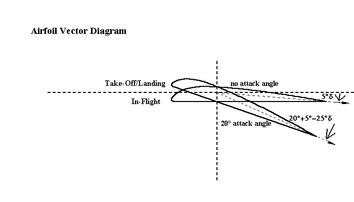
We are ready now to look at the view of the wing airfoil at two different attack angles provided in the figure below. In one, the airfoil is straight and level, the attitude of cruising during flight, and in the other, the airfoil is at a 20° angle of attack, assumed during climbs or descents when the speed is low. Notice the dotted line drawn to indicate the likely direction of the airflow as it comes off the trailing edge after the top flow and the bottom flow have merged. It is about at a downward angle of about 5° below that of the bottom surface of the airfoil in this representation.

So the deflection angle of the first case is about 5° and that of
the second case is about 20° + 5° = 25°. We are now ready to make use of the
Basic Airflow Force Equation by means of vector diagrams depicting the two cases
in solving for the force, F, with its components, L, the lift, and D, the
drag.
The vector diagrams are useful in depicting how the ÑV is found. The other term, the mass flow, can be thought of
as something proportional to V. What is happening is something that everyone
connected with flight knows: lift (and drag) in airfoils varies as V squared or,
here, V x ÑV. That is why aircraft velocity is so
important to flight. Aircraft speed is such a great convenience and it also
provides superabundant lift when its value is sufficiently large.

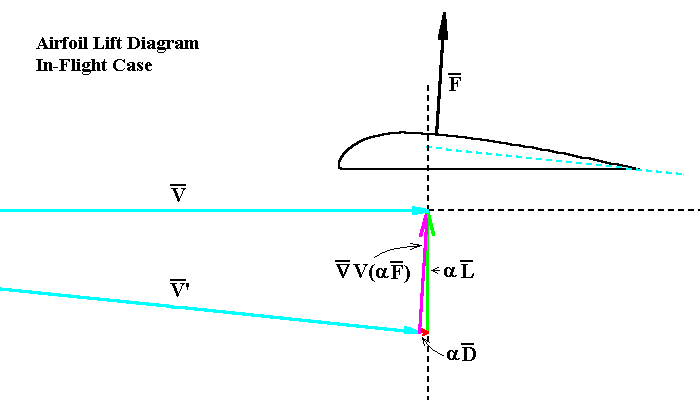
The first vector diagram, above, depicts the case in which the aircraft is in level flight at cruising speed. The V vectors are long and the deflection angle (-5°) is at its nominal value for the wing. V is the airflow vector before encountering the wing and V' is the airflow vector after encountering the wing and having been deflected downwards by it. (The V' vector is displaced over to the left far enough to have the same starting point as the V vector, which is how the vector algebra subtraction is done.) The purple vector is the difference vector, ÑV. It is proportional to the total force vector, F, acting on the wing. ("a" means "proportional to".) As mentioned previously, the force vector can be broken down to the lift vector, which acts in the vertical direction and is shown here in green (marked as "aL"), and the drag vector, acting in the horizontal direction and shown here in red (marked as "aD"). To be noticed here is that the red drag vector is quite short. In this case drag is reduced to only a very small fraction of the lift.

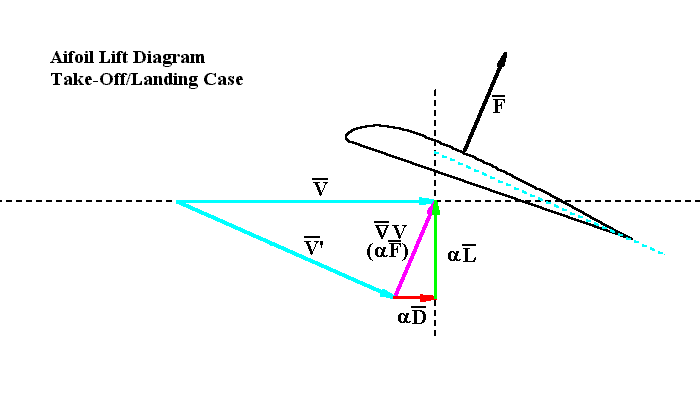
The second vector diagram, above, depicts the case in which the aircraft is traveling at a slower speed, perhaps either on takeoff or landing. The V vectors are shorter and the airfoil is set to a higher attack angle in order to achieve a higher airflow deflection, in this case about 25°, and maintain sufficient lift. Again, V is the airflow vector before encountering the wing and V' is the airflow vector after encountering the wing and having been deflected downwards by it. (Again, the V' vector has been displaced to the left.) The purple vector is the difference vector, ÑV. It is proportional to the total force vector acting on the wing, F. It is about the same length as the purple difference vector in the previous case. The lift and drag vectors are green and red, respectively (marked "aL" and "aD"). This time the red drag vector is much longer. The penalty for flying at a slower speed and higher attack angle is increased drag.
The Lift And Drag Formulae
Of great importance is the following lesson that is learned from a study of these diagrams. To attain the best performance of the airfoil in supporting the aircraft, the lift must be maximized in relation to the drag. Increasing the attack angle of the wing increases both lift and drag but drag is increased much faster. Therefore best results are obtained when the attack angle and, accordingly, the airflow deflection is reduced to the minimum necessary for the required lift. The geometry of the diagrams readily yields the lift and the drag and resulting expressions for them are as follows:
L = 2rCV2sin(d/2)cos(d/2)
D = 2rCV2sin2(d/2)
These expressions reinforce our conclusions above. The lift is proportional to the sine of the deflection angle (or, actually, half of it) but the drag is proportional to the sine squared. Again, the most efficient design for aircraft wings is indicated as being that in which airflow deflection is present but is minimized to that which is just necessary to maintain flight. It is easy to see how the popular misconception has arisen in which it is believed that airfoils operate with no deflection of the airflow at all. Deflection is always there. It is often just quite small and must remain so in most circumstances.
The Mystique
We are touching upon the mystique of flight at this point. What is flight all
about? We can see now that, as the wing passes through the air, it kicks it
downwards a little. This produces the necessary lift. In observing conservation
of momentum, it makes no difference whether a large amount of air is given a
slight nudge downwards or a small amount of air is given a much stronger shove
downwards. The same lift force is produced either way. But the energy
requirement is much different in each case. The kinetic energy of the air mass
put in motion is proportional to the square of its velocity. So clearly it takes
much more energy to give a small amount of air a more robust shove. Wonder of
wonders, that's what flight is all about. Aircraft and bird wings are designed
to encounter and process large volumes of air, the more the better, and impart
to it the least amount of motion downwards necessary, requiring thereby the
least effort. That's the whole story that falls out of this analysis and it is a
splendid one.
Earlier it was mentioned that the aerodynamics of flight
and the aerodynamics of wind energy are quite different. Now one of the reasons
in support of this statement can be seen. In flight, airflow deflections are
small and maintained so in order to minimize drag. In wind energy, as we shall
see in ensuing chapters, drag is not a consideration (actually this drag, termed "induced drag" has little significance, but another drag, termed "friction" or "parasitic" drag, does have importance) and so deflections are
deliberately set to be greater in achieving the necessary energy conversion efficiencies. But the vector diagrams used in this
analysis continue to have application and we will find that they stand us in
even better stead for use in understanding the aerodynamics of this newer
technology.