Highlights
Directory
Note: text size adjustments on your browser toolbar sometimes advisable.
Last Site Update:
December 19, 2017
A recently announced multi-element blade concept called the "Triblade" was added to the home page center column. It has importance as a first step in going beyond current blade designs in reaching higher levels of power ratings.
A drawing of a typical application of the "NoDrag Flap" was added to the main page central column to the right. This is a scaled up version of the small turbine double element blade concept which should be useful for earlier model utility grade wind turbines of the 75 kw or so ratings.
An initiative to possibly decommission and market some of the earlier midsize wind turbines may be considered here in the Tehachapi, California wind projects. The Vestas V17 turbine is described and offered for sale herewith. Open with the "Customer Data Base" link above.
Don't forget the earlier changes. A more complete treatment of the NoDrag Flap blade mod, earlier introduced briefly, is now presented. It brings into better understanding the difference between the ordinary wind, which is in the earth frame of reference, and the wind in the blade frame of reference, more appropriately known as the "relative wind", which is much faster and at a narrow angle of attack.
Also, the "Hands On(!)" page (link above) has now four videos with sound showing the early development of the double element blade concept done by IntegEner-W in small scale. These entertaining productions provide a good idea of how the blades look and how well the blades perform. This has been a basis for further work.

Titles of Earlier Subsections Removed
Wind Turbine Blade Airflow Deflection Under Analysis
The Issue of How Wind Energy and Aviation Differ
Converting Aviation's Wing Lift and Drag to
Wind Energy's Blade Driving and Thrust Forces
Solving For The Blade Forces That Matter
Air In Motion Does Not Want To Be Deflected!
The Kutta-Joukowsky Condition To Some Degree Invalidated
The Surprising Airfoil Aspect Ratios - Both In Aviation And Wind
Stream Function CFD Software in QuickBASIC
Aerodynamics Engineering Textbook Studies
Wind Energy Airflow Deflection Theory
(See pages one, two, and postscript.)
The Surprising Benefits Suggested by Theory of Pitching Blades
Not Positive, Not to Zero Degrees, But Actually Negative
Evidence From Practice
FRED A Wind Turbine Blade With a First Name
Designing blades with additional blade elements that reach an axial distance upwind of only 12% of the rotor diameter length is what would be necessary to achieve a "full rotor energy delivery" or "FRED" possibility.
The MultiElement aka "Wind Harvester" Blade As Providing Structural Reliability Against Excessively Strong Winds
Making Payments
To make the payment, go to the Contact Info box in the lower left hand corner of the home page. Click on the "Buy Now" button. A new website page will appear. Fill in the "Item Price" box with the amount agreed upon, such as "$9.99". Click on "Update" just below it and follow instructions if any. The price will then appear. Then go to the right side of the page and fill in the requested contact info and payment source data for PayPal. Expect a reply within 3 days.
The earlier material continues to be valid and is still available by means of email or telephone request. This is a free service and consists of receiving a copy of the last version of the website home page as it stood before this latest change. As always, the material is of academic interest, based on published work within the field as well as original work contributed by IntegEner-W. The subsection titles are all listed above. The copyright still holds but is subject to "fair use" as is acceptable under copyright law. There is to be no abridgement of privacy so long as the copyright is honored. The "Customer Data Base" and "Home Projects" website pages have not been given such abbreviation and so remain intact.

Multi-Element Blades To Be Scaled Up For 10 MW Turbines


The "NoDrag" aka "XP" Flap on 75 kw Wind Turbine Blade Tips
A Blade Upgrade For The Many Earlier Wind Turbines Still In Use


See the following material for a description of the airflow mass theories that govern the performance of the flap. A "fair use" exception to the copyright would apply to educational uses of this drawing such as in school and college course curriculums.
The Gurney Flap And Its Similarity To The NoDrag Flap
An Earlier Idea That Proves The Concept

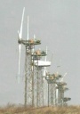
 The high TSRs at and near the blade tips of the large turbines evidently have a very high efficiency, as a general statement that may be made. Blade tangential speeds of up to 175 mph may be found there. But these high TSRs along with their efficiencies are, to say it openly, going to waste with the single element blades on all turbines. More wind can be captured and processed under these high TSR conditions with a second element separated from the first with a gap placing it some distance upwind.
This, after all, is the design of high speed hydrofoil sailboats that run close hauled to the wind. The jib and the mainsail are both necessary no matter the speed. These notes have always taken the position that sailboat sails are a better model for wind turbine blades than airplane wings are.
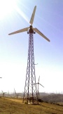
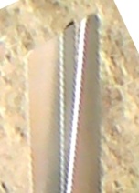
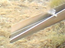
So the point being made is that it may be better to start developing double element blades from the proximity of the blade tips rather than the proximity of the blade roots. Here in the photo on the left is the blade tip of a successful small wind turbine. Notice how it resembles the mainsail and jib of a sailboat. This turbine ran under full load at such high rotor speeds (with tangential speeds of the same 175 mph as those of the large turbine blades) as to make clear an abundant ability to do so.
But some early theoreticians found what they believed to be a kind of lift that is produced with no drag. All of aviation immediately fell in love with this explanation. It made use of a so-called "gamma circulation" or rotational flow that sort of bounces off of the air beneath it. This is subject to questions. In briefer language saying the same thing it is the more familiar Bernoulli Effect that is heard so often that arises on Clark Y-shaped wing profiles.
So aviation makes use of both explanations of lift, one that is official but has some doubt attached to it, and the other that is never mentioned but may actually be the more important source.
But wind energy is an entirely different ball game. This selfsame deflection of the airflow created by the blade airfoils is actually what is the centerpiece of the energy conversion. It is so important to the process of delivering energy that it is to be maximized to the greatest extent practicable. This is completely the opposite of the case with aviation.
If the blades are pitched to zero degrees with a long, straight trailing edge, the wind is stopped in its tracks behind the blade, which means its kinetic energy is removed. A small residual velocity is still present moving in the rotor plane past the trailing edge, but this is necessary from Newton's Law. It is the reaction from conservation of momentum from the creation of a driving force in the blade.
It is hoped that this all makes sense. Wind energy is much more the subject of Newton's Laws than it is being made out to be. The Bernoulli Effect has no place in the creation of energy on wind turbine blades. The study of blades is being given second place compared to other mechanical factors involved with the design of wind turbines as if it is "a sleeping dog that should be left to lie".
From a purely aerodynamic point of view, ideal wind turbine blades would have little thickness, a curved leading edge, and a long straight trailing edge. This is quite different from the thicker blades often seen with camber placed in the middle of the profile. Others often seen are of uniform thickness while curved in a circular arc as if deflecting only the wind passing by in contact with the blade is all that is necessary.
There are actually two chores that must be done. There must be a curved leading edge around which the wind changes direction, accepting a low pressure there for a driving force. (It is the flow direction change which causes this low pressure, not the often mentioned Bernoulli Effect, in this case. But this is obvious. Any fan blades do the same in reverse.) The second chore is that the wind must be solidly restrained to move all together, nearby and far away, in the new deflected direction. It is like the wind will misbehave because conservation of momentum makes it want to resist any changes in direction. So the trailing edge must be long and straight as an arrow, making for a no nonsense imperative to the wind to altogether observe this new flow direction..
Maybe a name can be given it. It is certainly not the Clark Y profile. Blade thinness was found to largely reduce parasitic drag, something not available with the thicker Clark Y. But it is a profile all of its own. Some thickness may be needed for structural strength reasons.
But there is more. Since there are two chores that must be done, it is only logical to provide two different blade elements that are assigned to the two chores. They are then separated from each other with a gap. Thin, single element blades are not as likely able to support blade bending moments as are double element blades separated by a gap. This is another good reason for double elements. That about tells the story of how the double element blade design came about.
Airfoils Attached Alongside Blades On The Upwind Side With a Gap Between
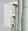
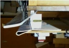
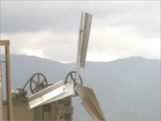 The private sector, maybe the name of how this is being done, uses plainer language in describing technological development. A local homeowner became one successful wind turbine double element blade user for his energy needs. The photo clearly shows the early design as it was being tested.
It is becoming clear that wind turbine rotors do better physically with blades with forward elements stacked ahead of them upwind such as is shown here and is the basis of the "XP Flap" being discussed. This is as opposed to wider blades, which tend to block the wind, and additional blades, which are expensive.
Having proven both in terms of practice and aerodynamic analysis the benefits of added blade elements, the future of this blade design seems clear. With the help of those willing to participate in development, this technology is headed for more study and implementation.
This "new" airfoil profile for the "XP Flap" blade element has never been seen or given analysis before. It is a mostly flat piece of sheet metal or other material with a rounded leading edge and pitched to zero degrees. How simple is that:
It doesn't add or contribute to the Bernoulli Effect by itself in the slightest. The flow on either side is at or nearly exactly the same velocity. There is little surface and that is only at the very small tip of the leading edge that can possibly support any reduced pressure directed to produce a driving force. Theories covered in all of the well known physics and aerodynamics textbooks by all of the well known authors have never mentioned anything like this. Wing ailerons and flaps are almost always connected to the wing itself. This is not.
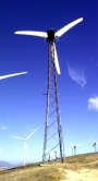
 Yet, when added to well known small turbine blades in use and covered on websites such as in the photos on the left, it produced and continues to produce in turbines in use today such a great improvement of the speed of rotation and torque as to defy belief. These 30 inch long blades run readily in 20 mph winds (30% of 30 mph rated wind speed power) at 1000 rpms, i.e. 175 mph tip speeds, producing excellent power at this lighter wind speed and not far from the Betz Limit. The tip speed of 175 mph on these short blades even so is about equal to that of the tips of the large 50 and 65 meter blades on the 3 MW and beyond wind turbines. Amazing.
Objections heard had been that the wide flaps, pitched to zero degrees and having no "aerodynamic" profiles, would add nothing but drag to the turbine rotors. That is why, in order to provide a statement to the contrary, they were originally called the "NoDrag" flaps.
The "XP Flap" is just a flat piece of sheet metal with a folded back leading edge added entirely outside of its blade and pitched to zero degrees. As such, it is given no notice in traditional theory. How can anything like that have any value is how it is treated. Seen instead ordinarily are little more than variations of the Clark Y profile of the basic wing or blade.
What needs to be said in no uncertain terms is how well this simple flap increased power when added to the blades during testing of small wind turbines.
The reason, of course, is that it adds flow deflection that acts not on itself but on the leading edges and surfaces of the main blade in a partnership that produces so much additional driving force.
It fell out of our small turbine hands on work as easy as pie. Small turbines with these blades are in use here in Tehachapi and available for viewing. The idea is becoming understood popularly here in the private sector by those with or without technical training.
Is this blade flap, now identified as "XtraPowr Flap" or even "XP Flap", going to actually be added to existing technology:

Amazing is that the power produced can be increased by increasing the width of the gap between the flap and the blade, here being 4 inches. It can go to 6 inches or more to access more wind mass flow with the narrow tips. It is a dimension never used before. Only by lengthening blades has power heretofore been increased.
The "NoDrag Flap" described hereunder is within the category of a blade second element feature.
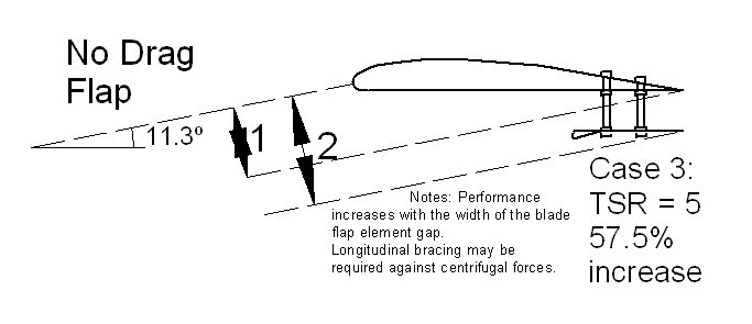
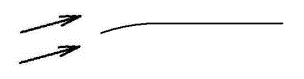
Blade Cross Section with the Approaching Relative Wind at a TSR = 5
For example, a blade tangential speed of 150 mph and a wind speed of 30 mph
Now look at what is happening. The attack angle is so small that even with a wide blade the approaching airflow sees ahead of it or "faces" only a blade dimension that is equal to "1" in the diagram. To widen the blade for more airflow to face it would take a much larger blade chord dimension with little effective gain in blade faced by the airflow. The idea herein is to keep blades narrow and yet provide plenty of airflow deflection as if the blades were wider.
But if another blade element were to be added beneath the trailing edge as is shown above, much more effective blade width would be gained with little cost or increase in actual blade width. The blade dimension that is faced now would be equal to "2" in the diagram, which is 57.5% larger than "1".
This also makes the blade effectively 57.5% wider in encountering the wind without making the blade actually wider in this case. More wind is deflected and greater power is produced. Included in this website are evidences from testing and practice of successful implementation with improved performance of second element mods such as this to blades.
That May Bear on Wind Energy
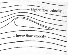
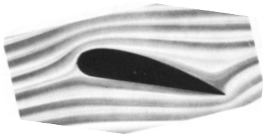
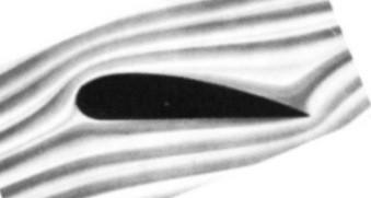
Drawing From Airfoil Theory vs. Photo Of Actual Streamlines
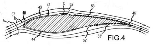
Drawing From Wind Blade Patent Application vs. Photo Of Actual Streamlines
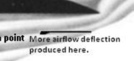
Added to this is the missing fact that the airflow velocity is not only increased above the airfoil near the leading edge as indicated but is increased also beneath the airfoil near the trailling edge, which causes a lowered pressure there as well.
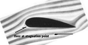
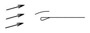
 Corrective measures are sometimes being considered. The vortex generators introduced on the downwind sides of blades have the purpose of increasing the Coanda Effect. However, experience has shown a relatively small effect gained. A possible solution is offered by a second blade element. The element may be a thin flap added under the trailing edge as superimposed in the photo - as is - on the left.
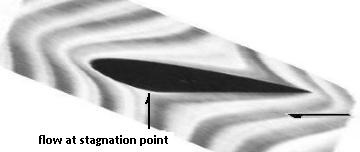
In the image on the right, a better view of the potential effect of this second element is gained. An approximate conversion of the image to the Earth Frame of Reference is obtained by means of skewing. The flow attack angle ahead of the stagnation point then is fixed at minus 90 degrees beneath the airfoil to eliminate the blade tangential velocity vector. It becomes quite clear that the additional element beneath the airfoil moves to the rear providing more effective blade width as shown. If the flow streamlines were adjusted to suit, a better deflection of the entire trailing flow downward and closer to the blade chord line would be seen. Greater airflow deflection, of course, means more power production.
Answers such as this are needed. Small one kilowatt turbines using double element blade concepts have been a remarkable success. Shows to go (!).
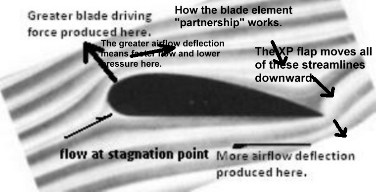
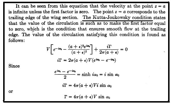 The theory which sets the flow lines to follow the airfoil surfaces closely and leave the trailing edge smoothly following its direction is found in early aviation theory publications¹ (page segment copied in "fair use" on the left for review purposes).
What is happening here is that a "clockwise flow circulation" has been postulated around the airfoil profile. The strength of this circulation, termed "gamma" and notated by the Greek letter Γ, is being determined by how well the flow thereby adjusted deflects sufficiently to leave the trailing edge smoothly. This has been given a name: "The Kutta-Joukowsky Condition".
The value of gamma found thereby is seen as the last line in the analysis. But the underlying assumptions have made this analysis superficial and unwarranted. The flow has momentum that overrides any circulation present. The actual value of this parameter can not be found in this manner. In fact, the actual value has never been adequately studied and found as is presently known. There is some deflection occurring but how much is a more complex problem than this. Suffice it to say that this logic has been given more credence than is justified. The evidence from practice now demonstrates that the "Kutta-Joukowsky Condition" is not a valid deflection theory hypothesis. Wind turbine blade design is better approached without it.
And yes, small wind turbines can sometimes readily and quickly cover gaps in the theories. Small is beautiful (!).
¹ From page 52 of Theory of Wing Sections by Abbott and von Doenhoff, 1959, ISBN 486-60586-8, Dover Publications Inc., Mineola, NY.